JD 620 power steering pics

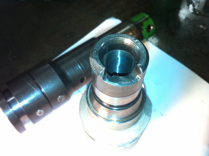
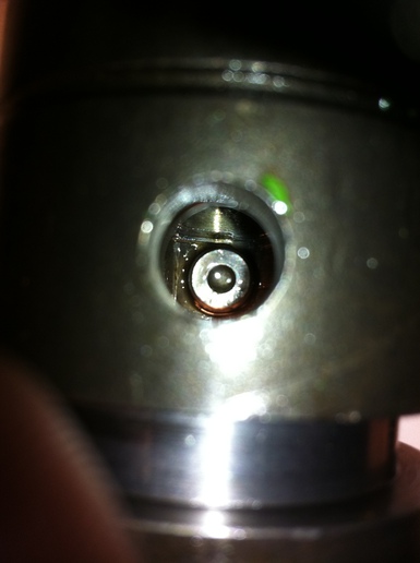
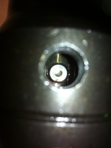
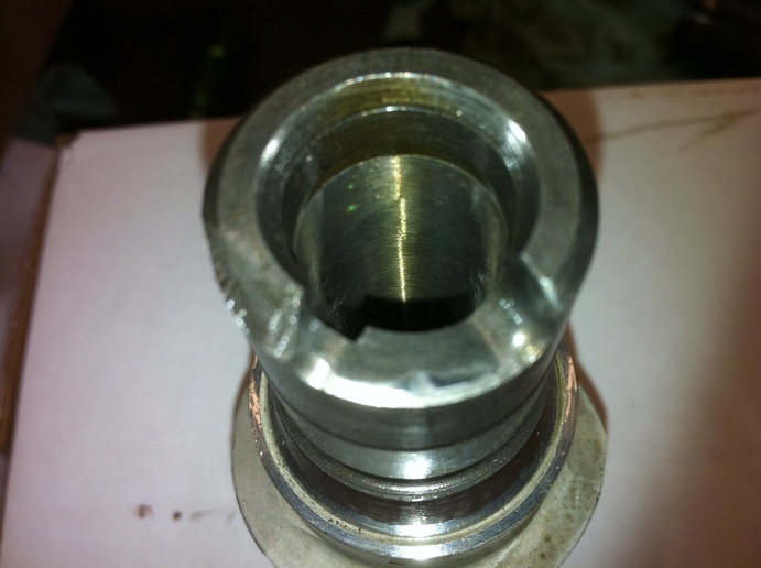
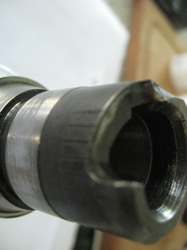
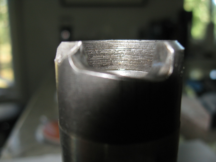
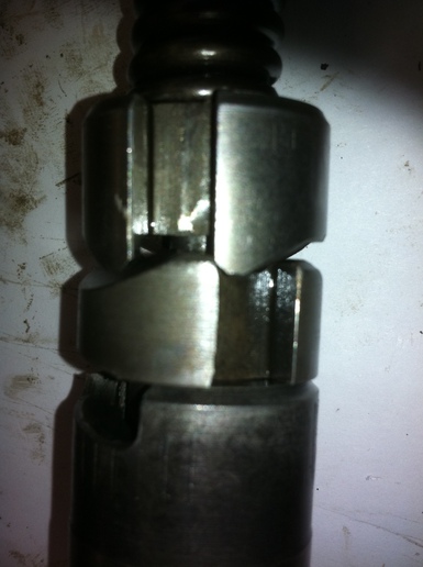
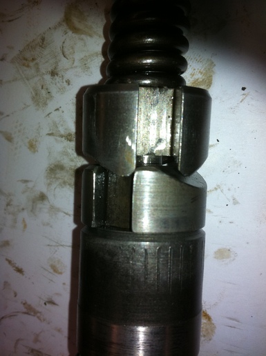
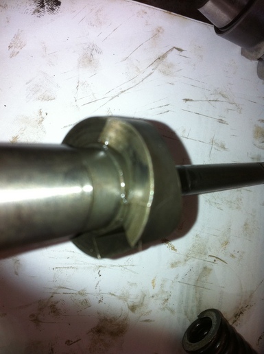
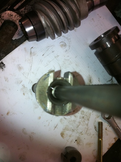
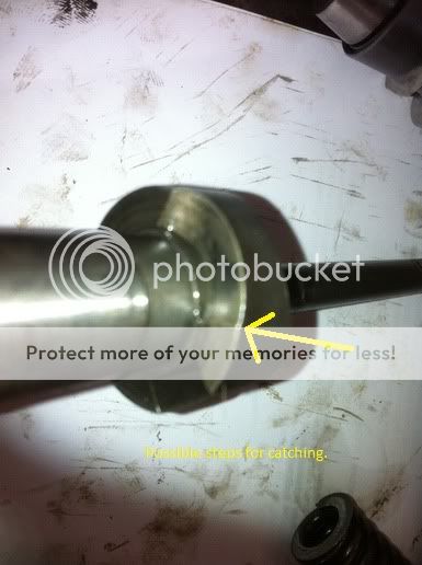
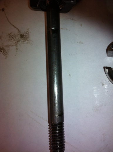
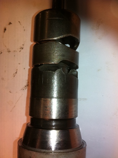
Assembled the cams, shaft, spring held in place with the nut, not tightened to original tension -the wear on the cam stud/rod -when the moveable cam is turned, the corners catch on the stationary cam -slid the assembly in the sleev and rotated it with vice grip attached to non machined surface -the shaft had a distinct catch everytime rotated - will try with spring properly tensioned -my thought is that the moveable cam bore is quite loose on the rod/stud in additional to the wear groove on the stud and wear inside sleeve allows cam to tilt enough so that the corners catch while rotating -I will clean up all the surfaces -remove burrs and level out divots -ordered new dowel pins even though very little wear on present ones -and flip the rod/stud end for end to get vway from the wear groove and try rotation--
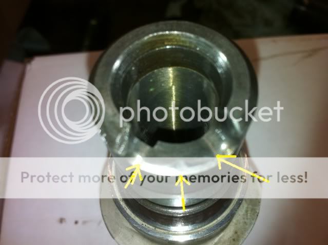
Are the corners of the moveable cam supposed to be beveled or square -bevelled due to wear?
Best tool to use fine file, emery cloth, stone -?
Ken
a77652.jpg

a77653.jpg
 
WOW, Ken! You're looking at the wrong place! There is/was a cam face on the end of the worm, and it is broken away! That's where the other pin rides.

Unless I'm seeing it wrong. Disassemble that group and let me see the worm cam face straight on and side ways, and the same for the other cam. Those two things you are looking at above act as sort of a slip clutch to determine how much force it take to begin assist.


Ken.jpg
 
Sorry Frank, but it my first power steering repair -thanks for any help-I did notice the cam face broken away, but it is not broke out full depth -when i compress the spring to former length and turn the moveable cam, the cams overlap and jam -yes it is out of the sleeve, but with internal wear in the sleeve i think this is also happening causing the catching - i am showing both dowel pins as well
a77669.jpg

a77670.jpg

a77672.jpg

a77673.jpg

a77680.jpg

a77681.jpg

a77682.jpg

a77683.jpg
 
The faces have to be stoned smooth. I use a high rpm air die grinder, and a 1/4" stone. The form is basically a 45* slot, slightly less than a 1/4" wide, formed to fit the 1/4" dowel pins at the end of travel. Arrows show where I would stone out for catching.

Cam1.jpg


Cam2.jpg
 
F-I-T,
You are right, the end of the helix ramp should be repaired or the worm replaced. With that corner broken off you have a problem with the pin jumping over that edge and sticking there.At sometime someone really put some pressure on this worm to brake that corner off. The reason it only broke the out side is that the pin does not go all the way to the bottom of the helix slot
The rounded corners are for manual operation of the steering.

Rich
 
I was thinking that maybe Ken should ink that worm cam surface with a magic marker, or layout die if he has it, then assemble it and crank it back and forth several times. Then take it apart and examine the wear pattern. My guess is that it shows up where my arrows point. He can reclaim that worm if a good Tig job is applied, but I sure would look for a replacement, and redress that one. You're right, it sure took a hard hit at the extreme left or right, whichewver it is. Surprised it didn't crack that hardened dowel.
 
I have seen simlar breakouts on those before. Seen a few split clear down the keyway too ! The improved design is not an improvement in that area.
From new they were never profiled properly to get full contact with the pin on that one end. They only hit the corner. when I build them back up and dremal them to shape I like to keep working to get full contact.
 

We sell tractor parts! We have the parts you need to repair your tractor - the right parts. Our low prices and years of research make us your best choice when you need parts. Shop Online Today.

Back
Top