Power factor a well pump

Geo-TH,In

Well-known Member
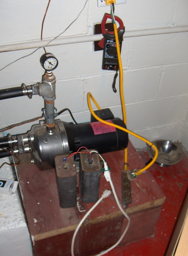
There has been a lot said about power factoring motors, so I had some time to play in my cool basement. My well has a 3/4 hp A O Smith pump. It operates on 120v. I put a 12 gauge cord on it by buying a 6 ft extension cord and cutting 3 ft off the end. Took the other end of the cord and put a plug on it. Removed some of the insulation so I could put ammprobe around the power wire. Plugged my pump in the end of my 3 ft extension cord.

To my surprise, when the pump kicks on around 20 psi, my amp draw is close to 15 amps. As the pressure builds, the amp draw decreases to 12.2 amps. The more the pressure, the less the amps. That seems odd to me, I would have thought just the opposite.

I have 2 55 mic 440 Volt capacitors. By connecting a capacitor to the end of the white cord, I could plug the capacitor into my 3 ft extension cord and also have the well pump plugged into the same cord. This puts the 55 mic in parallel with the pump and the total current decreased by 1.1 amps. Putting the second 55 mic cap in parallel with the first, my total current went from 12.2 amps to 9.99 amps. I was impressed with my results. Even had a little excitement too, especially after unplugging the capacitors and shorting them. I confirmed the big ban theory.

Going to get a metal box, some bleeder resistors, fine tune the bank of capacitors for minimum current and install them on the side of the switch where the pump is connected.

Next I tried to power factor a 4 peak hp electric chain saw. My results were the opposite of my well. Adding any size capacitor caused my total current to increase. I started with a 4 mic and stopped with a 55 mic.

So, are you not able to power a universal motor?

Are you not able to power factor a universal motor that's not under load?

I'm sure there are some will say that I don't have a clue what I'm doing, so I'll put that out there as one of the options.

Like to hear what are EE, John T thinks too.

George
a78489.jpg

a78489.jpg
 
Hi again George,,,,,,,

So, are you not able to power a universal motor?

Are you not able to power factor a universal motor that's not under load?

Hey my very first job out of EE school was as an engineer for the Century Electric Motor Company buttttttttt that was 42 years ago and I forgot most of all that lol After that I got into electronics some but then years in the field of Power Distribution Design which I recall much more then motor theory..

I cant answer your questions, I cant see off hand without having to dust off my old engineering books, why adding capacitors isnt working here but if I get time I will study some on this...

John T Gettin old n forgetfull
 
36 coupe,
I'm full time retarted and have nothing else to do. Thought it was interesting that a pump uses less power the more pressure it produces. Did you know that? Also thought it was interesting that I wasn't able to powerfactor a universal motor. Did you know that?

I would go plow, but the ground is so dry, the plow wouldn't go in the ground:)

George
 
I think it's because as the pressure increases the volume decreases. If it were a positive displacement pump it would be the other way around.
 
Okay so this dumb ag student finally caught on to what your doing 1- experimenting-the challenge is more important than the result, at the end of the tunnel is knowledge. 2- by "starving" the pump of voltage you're forcing it to start SLOWER and thus not grabbing as many watts and stressing out your generator. Adding a couple of Omron timers or such you'll have a genuine home grown soft start.
 

To my surprise, when the pump kicks on around 20 psi, my amp draw is close to 15 amps. As the pressure builds, the amp draw decreases to 12.2 amps. The more the pressure, the less the amps. That seems odd to me, I would have thought just the opposite.

[color=darkred:4a3c10e95b]Yep this is a non-positive displacement pump, specifically a centrifugal pump. There is no sealed displacement area in this type of device the water is just slung around the volute area, and as pressure builds there is increased slippage back around the pump rotor and volume output drops off.

If you valve off either the input or the output the motor current will drop.
The same thing happens with centrifugal fan or blower blocking off the air flow will lower the motor current. [/color:4a3c10e95b]

I have 2 55 mic 440 Volt capacitors. By connecting a capacitor to the end of the white cord, I could plug the capacitor into my 3 ft extension cord and also have the well pump plugged into the same cord. This puts the 55 mic in parallel with the pump and the total current decreased by 1.1 amps. Putting the second 55 mic cap in parallel with the first, my total current went from 12.2 amps to 9.99 amps. I was impressed with my results. Even had a little excitement too, especially after unplugging the capacitors and shorting them. I confirmed the big ban theory.

[color=darkred:4a3c10e95b]The lagging current in the induction motor is being PF corrected by the leading current flow in the capacitor, over correction with too large of capacitor will begin to create a leading PF and as the PF shifts from lagging to leading the current will begin to increase as the PF passes through unity.
Separate the leads going to the capacitor and the motor and with your setup use your ammeter to monitor the current flows into and out of the capacitor, the line, and the current flows into and out of the motor. [/color:4a3c10e95b]


So, are you not able to power a universal motor?


[color=darkred:4a3c10e95b]The torque developing current flows are not induced in the series universal motor but are a result of current flow in the series field and armature circuit therefore the motor current is nearly in phase with the line voltage. So there is no out of phase current to phase correct.[/color:4a3c10e95b]
 
The power required to run a pump is proportional to pressure x volume. As the pressure increases in your tank, the volume drops off. If you were to connect your pump to a valve and an open pipe, you would find maximum current draw when the valve is fully open and minimum draw when the valve is open.

It makes no sense to try to adjust power factor under no load. The whole point is to lower the current requirement, so you want to do it under a typical load. Let's take the extreme case: you have the motor disconnected and add capacitance to the power source. Immediately the current will increase because the capacitor by itself has a very low impedance. Now you may be adjusting the power factor for the rest of your house, so the current at your meter is less, but it's not doing anything for the motor's PF, since the motor isn't even in the circuit.

I suggest you pick up a "Kill-a-Watt" meter; it's the cheapest way I know to measure power factor.
 
I knew about fans, just didn't didn't think it applied to a pump. I use old furnace fans in my shop. Discovered that blocking off the discharge a little speeds up the fan and decreases the current.

You have given me an idea. I'll try turning down the valve on the discharge side a little and watch the amps. Some critics here think what I'm doing is crazy. My crazy goal is to run my well with a small 3250 watt RV generator and not damage either. I used to power my well with 220 and never noticed the lights in my house dim. My house has new 200 amp service and new wiring. So, it concerns me that after going back to a 120 v pump, my lights dim just enough that I notice it. To me, the dimming indicates a large lock rotor amp draw.

Before doing this experiment today, I thought my pump would use less power if I tried to start it after my water pressure went to zero.

Separate the leads going to the capacitor and the motor and with your setup use your ammeter to monitor the current flows into and out of the capacitor, the line, and the current flows into and out of the motor.

I have a second ammeter and I'll try that too.

Thanks for your input and thanks for having a positive outlook on life. Wish there was another place for the grumpy old men to go!
George
 
Where I live, there are 4 families that share the same transformer from public service. So if I were to connect a large capacitor to my 220 v, have no motors running, would I be power factoring any 220v motor my neighbors are running, like there centeral A/C?

If it does, then will the capacitor's current be running backward through my meter? Will this current cause my meter to go backward if I had nothing turned on?

George
 
Take the vacuum cleaner out of the closet, turn it on (with a clean bag) it will make a moderate pitch sound. Put your hand over the inlet hose, and the motor will wind up several hundred RPM. (though this is a universal motor, and not induction, the principle of the non-positive displacement pump provides solid evidence. When pulling against a plugged hose, the impeller turbine is in a partial vacuum. EX 450 Owner is spot on and a good writer. Jim
 
George, capacitors are energy storage devices. Any energy your capacitor stores off the grid will be returned to the grid, 120 times per second.

Your meter measures power, not volt-amps. That's true whether the current is leading or lagging voltage. Let's take three examples:

1. Motor not adjusted for PF, so let's say PF is .7. A one-horsepower motor needs 746 watts, but 1066 volt-amps.

2. Motor adjusted for unity PF. Now the 1 hp motor draws 746 watts and 746 VA.

3. Motor turned off but the PF capacitor is still in the circuit. Power is now zero, although the VA will be greater than zero (not enough info to solve for VA in this condition).

The meter compensates for the phase angle between current and voltage, so you only pay for power, not VA. The power company doesn't like a lagging power factor, because it costs them money due to line losses and increased transmission capacity requirements. Leading power factors are seldom seen in the real world.
 
Hello George Marsh,
You did not check the voltage before and after the test.
Anytime a cap is used as you did the voltage is usually higher. That would explain the lower draw as the voltage would be higher. Higher voltage lower amperage, maybe the same wattage.
You now should check volt amps with and without the caps.
I bet you the VA will not be that much different
between the two setups.
Guido.
 
Gudio,

There isn't much variation in my voltage with or without caps. My load center is 30 ft away from pump. It's new 12 g wire. I finished the job this morning, mounted a metal box to the wall and put capacitors inside. I used two 55 mics, one 35 mic, and one 25 mic. Total amps dropped about 3 amps down to 9.5 from 12.3. Pump seems to start easier. The lights in my bathroom used to dim just slightly. Can't notice a thing. The capacitor amps is around 6. I installed a 10 amp fuse in the capacitor line along with a bleeder resistor.

I'm happy with the results and the way I see it, I'm the only one that I have to make happy:)

thanks for your advice and have a good day.

George
 

We sell tractor parts! We have the parts you need to repair your tractor - the right parts. Our low prices and years of research make us your best choice when you need parts. Shop Online Today.

Back
Top