Piston ring compressor update

SVcummins

Well-known Member
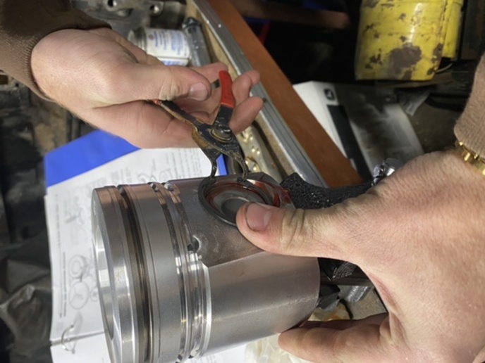
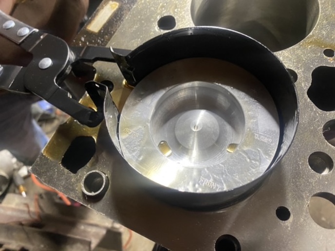
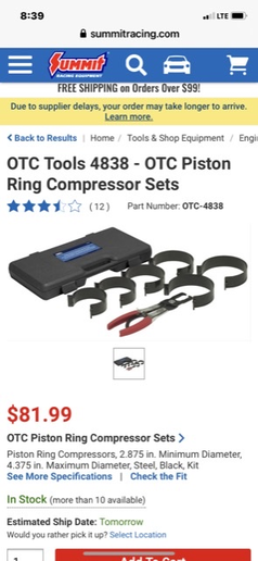
Finally tried out the ring compressor and hammer boy do they
work slick .
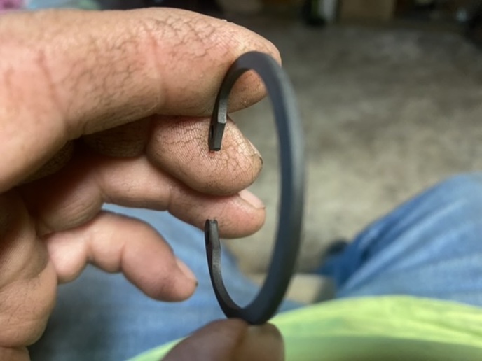
cvphoto104228.jpg


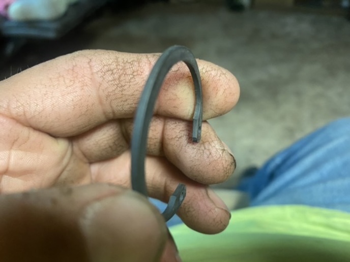
cvphoto104229.jpg


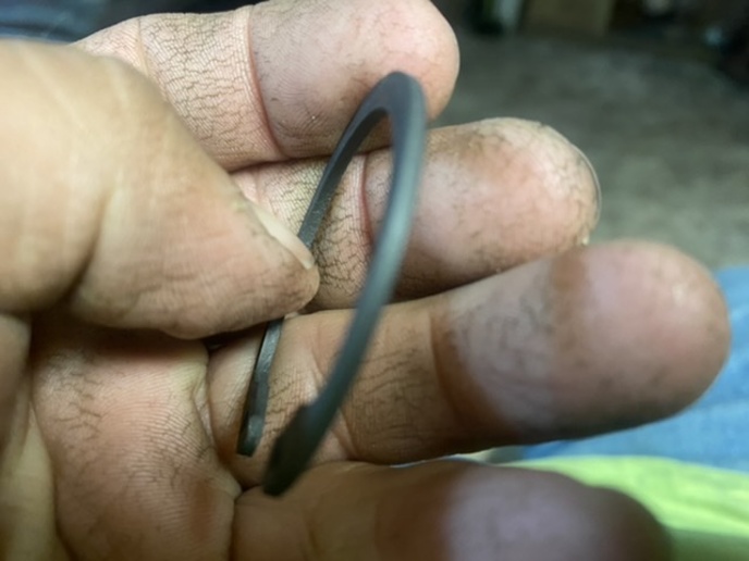
cvphoto104230.png


cvphoto104231.png
 
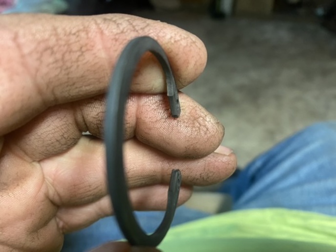
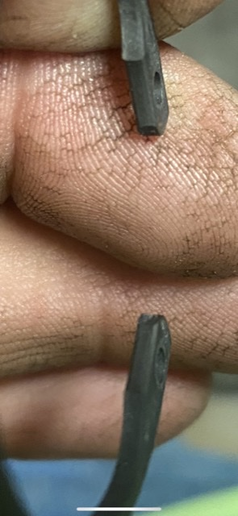
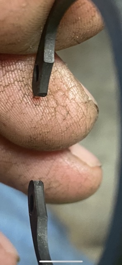
i see u have a mistake right off the bat, if thats how you installed them. the snap ring OPEN END always goes to the BOTTOM sideways or up and with the Firing Vibration on TDC can make the snap ring jump out.... also the sharp or square side of the snap ring goes out . all snap rings have one side rounded and one side square. dont want you to have a snap ring pop out and wear 2 grooves in the sleeve. then u be pullin the engine again. i had a 1974 ford 390 engine do that years ago.
 
I have never heard of that one before . These Are snap rings for dummies because both sides are square .
cvphoto104235.jpg


cvphoto104236.jpg


cvphoto104237.jpg


cvphoto104238.jpg
 
i would say i learned this about snap rings in 1977 when i was apprenticing for mechanic's ticket. its not something i just made up. and i follow through on it every time. same as ring orientation on piston rings. you might think the snap rings are both sides square but they are not. lots and lots of people don't know that and say the same thing as you. one side should be sharp square and other side has a slight taper close to the edge. we were taught that right in class. yes if you just pick it up without a close look you would never know the difference. its not clear to see in your photo's cause the pic's are fuzzy. both things i said are important in an engine. guess you could investigate it your self also. just giving you some important info.
 
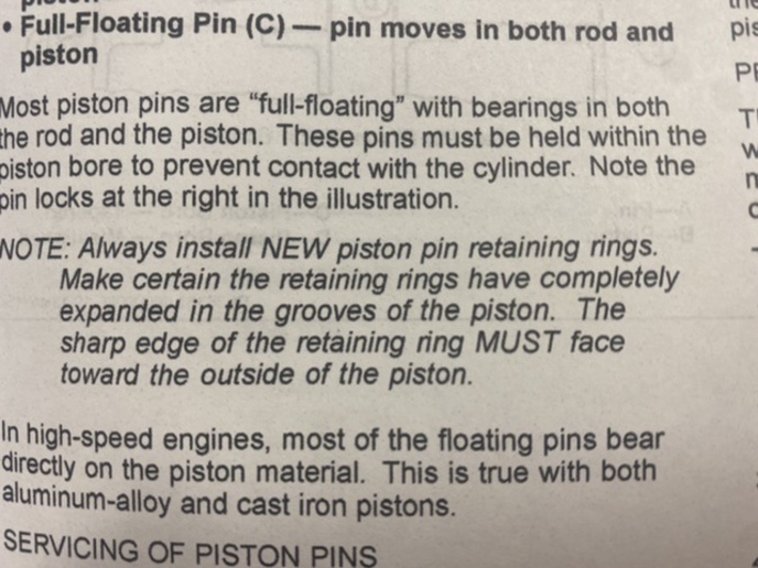
If one side is different I am in lot of trouble because I cant see one edge sharper than the other . Ive seen other snap rings that you could see a flat edge and a round edge but not these .found mention of it in the John Deere manual but no mention In the cummins manual or instructions with the pistons
cvphoto104241.jpg


cvphoto104242.png
 
they are saying the same thing i am flat side out, but i cant see your snap rings. they specified it also. guess if yours are both flat sided then thats a first for me then. its the outer edge that you look at where the pressure is pushing on the snap ring in the groove. maybe try a different pic with your snap ring out side in photo's. plus make sure the open space of ring is facing down, not sideways , not up.
maybe pete 23 has lots of hands on experience can verify this too, or anyone else who definitly knows. i just knew this, now started to look it up and i saw totally wrong explanation on u tube or they dont know anything about it. one goofball said its for the ease of using snap ring pliars, stupid azz , that why i question most of that u tube stuff. so it must be a dying art that went away with the j. d. 2 bangers. lol.
 
I dont put any stock in YouTube I prefer the factory service manual and if someone else has done it before . Ill look again . Not tonight three inches of snow out . The factory manual makes no mention of sharp side of the snap ring and I cant seen any difference
 
Those may be precision ground snap rings.

Typically the round or sharp edge is a result of the ring being stamped out of a flat sheet. It's a naturally occurring deformity of the metal.

But on a precision ground ring, the part is ground flat on both sides so there is no round or sharp side. An inspection with a magnifying glass would tell the story.
 
I suppose I will take your word on the snap rings being squared off the same amount on either face. As far as the placement of the gap between the ..installation eyes.. the downward position as in towards the skirt of the piston is the preferred location. However in this particular application if a piston has already been installed with them installed at some other orientation I would not go to the effort to remove one to change it. By doing that you are introducing the possibility of other damage factors like dinging a bearing half or ring damage. I do not think SV will be running a 400 - 1000hp tune on this engine.
Nor will he be spinning it up to some ungodly rpm over stock. That placement will only come into play by piston speeds created by rpms over say 5000. Of course that is also dependent on the stoke length of the crank. The only thing I see wrong is the ..tool box grung.. should be cleaned off of your snap ring pliers so it does not get transferred into the engine assembly. My two cents.
 
now i can see them. you are safe they are as steve said. maybe cummins has one of fords better idea's. lol. as for piston snap ring position that is due to the explosion vibration force's at tdc , not rpm. least that is what i was taught so im sticking with it. just for kicks next time on your machinery have a look at a snap ring.
 
Steve has it on the rounded or sharp side edge of the snap rings. If you feel for it on the outside edges you can usually feel one side is just a bit sharper at the edge. The other will have a slightly less sharp edge to it. I have not seen a reference to the side to use though. I usually put the sharper edge away from the thrust side on anything I use them in. I think it holds better in the groove. Also never heard of a particular position for the snap ring gap on a wrist pin hole either. Not saying it doesn't exist just never heard of it.
 

We sell tractor parts! We have the parts you need to repair your tractor - the right parts. Our low prices and years of research make us your best choice when you need parts. Shop Online Today.

Back
Top