
Anonymous-0
Well-known Member
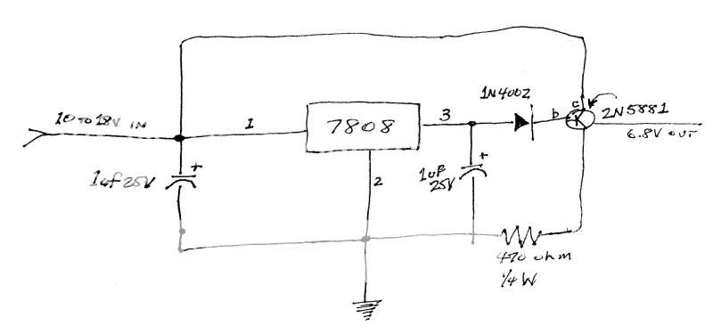
I have a diagram someone sent me a long while back when I was searching for in Instrument Voltage Regulator for converting the old King-Seeley gauges in my old International from 6V to 12V, without letting the smoke out of either the gauges or the senders.
Parts required include (1) 7808 voltage regulator; (2) 1 uf 25V tantalum capacitors; (1) 2N 5881 transistor, and a corresponding insulating washer/transistor socket; (1) IN4002 diode; and (1) 470 ohm 0.25 watt resistor. Not counting the heat sink, which wasn't priced, the original diagram came with a parts list that total around $8. Unless prices have gone haywire, today it should be able to duplicate for under $10, I would think.
According to my friend the electronic expert, this should change a 10V to 18V input to a 6.8V output, and according to him, there should be no worries about voltage spikes.
So does anyone WITH ELECTRONIC DEVICE EXPERIENCE agree with my friend? Should this work as he says, as long as an adequate heat sink is used?